

AI Megawatt-Scale Rack SiC Schottky Selection: From VF Comparisons to Package Thermal Resistance Certainty
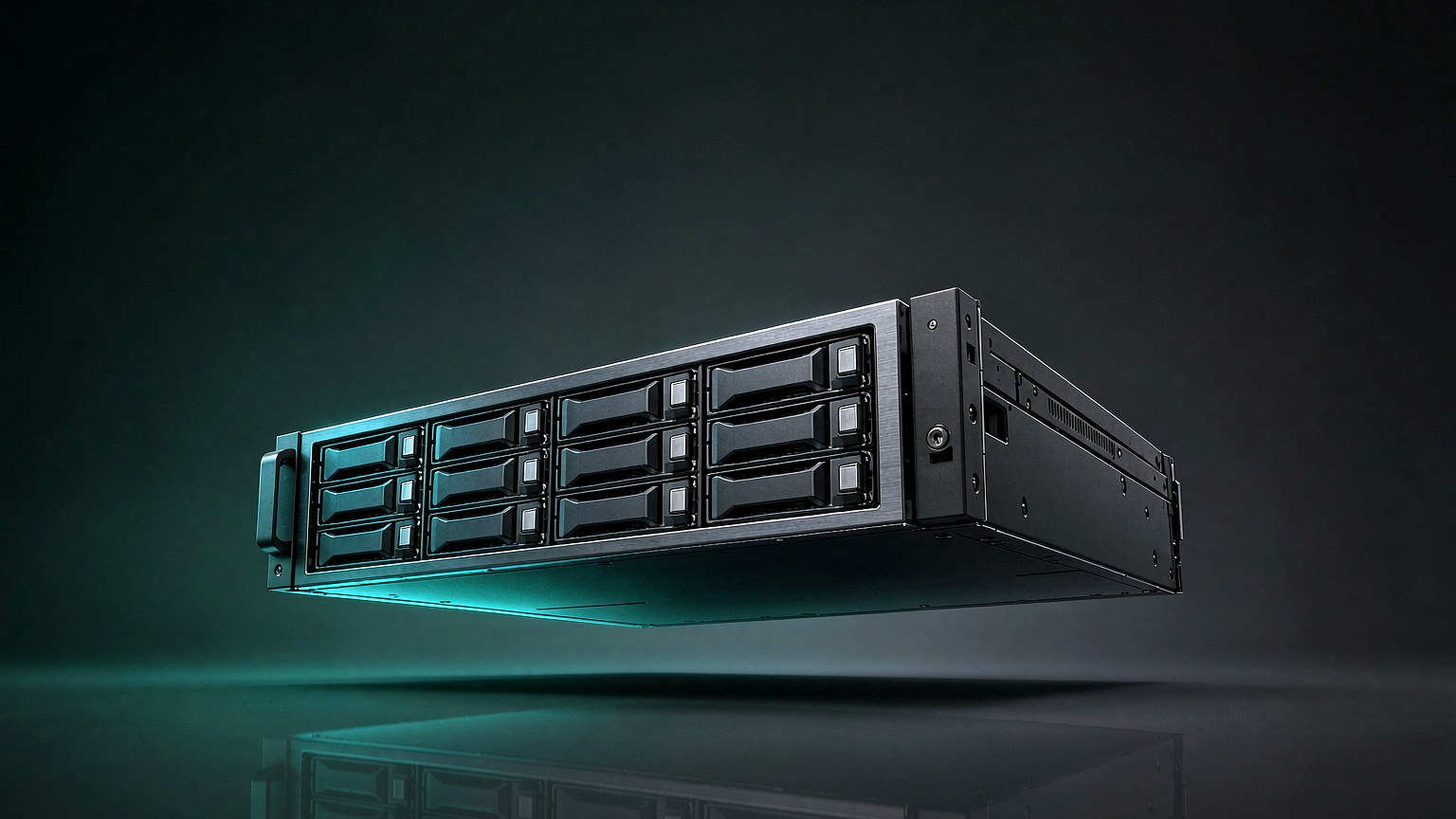
AI rack power is scaling to megawatts. Traditional 54 V low-voltage, high-current distribution is limited by copper loss and busbar size, driving data centers to 800 VDC. SiC Schottky module selection focuses not only on nominal VF but on **reproducible Rth (j-c)** and controlled parasitic inductance. Factory-stage multi-chip thermal coupling and internal wiring let MW rack multi-branch thermal design avoid post-PCBA empirical fixes. Chaoxing Semiconductor M45 **HS11UDA400N2X100** is typical.
1. 800 VDC Architecture: Schottky Diodes Evolve From Loss‑Optimization Parts To Architecture‑Enablers
Global market for SiC power modules for AI data‑centers shows strong growth. Industry statistics estimate the market size at USD 190 million in 2025, projected to reach USD 1.4 billion by 2032 with ~29.8 % CAGR. Growth is driven not only by component‑level efficiency gains but also by architecture‑level power‑chain compression.
Traditional multi‑step conversion “AC‑UPS‑AC‑PSU‑DC” approaches approach physical boundaries of copper loss and bus‑bar size for 100 kW‑class 54 V racks. Raising bus voltage to 800 VDC reduces operating current for equal power; copper loss scales with the square of current and decreases significantly. Meanwhile, front‑end rectifiers and high‑voltage DC‑DC converters impose stricter requirements on device blocking voltage, thermal management and parasitic parameters.
Public industry sources indicate NVIDIA is pushing rack‑power adoption of 800 VDC. The 800 V HVDC sidecar power‑supply concept presented at GTC 2026 is regarded as the near‑term mainstream solution. The industry calls 2026 “the year‑one for 800 V HVDC”. First‑generation units target 660 kW, with roadmap expansion toward 1.2 MW. This means Schottky modules face not incremental “millivolt‑level VF reduction”, but system‑level challenges: doubled per‑rack power, increased parallel branches and tighter thermal margins.
2. Core Value of Module Packaging for MW‑Level Systems: Locked‑In Thermal Resistance
Discrete power devices still offer layout‑flexibility for hundreds‑of‑kW applications. As rack power moves into megawatt range and parallel‑branch count grows beyond two‑to‑three branches, actual thermal resistance of each soldered discrete part becomes a post‑assembly variable sensitive to PCB mounting quality.
The engineering merit of power modules does not mean they universally out‑perform discrete devices. Modules fix multi‑chip thermal‑coupling and internal‑trace parasitic characteristics at factory‑stage, with well‑specified Rth(j‑c) junction‑to‑case thermal resistance in datasheets. During pre‑layout simulation, engineers can estimate junction temperature from measured case temperature using published parameters, without waiting for PCBA hardware and thermal‑camera debugging.
HS11UDA400N2X100 (M45 package / 200 V / 400 A / typical VF 0.95 V / IFSM 3300 A / Non‑isolation SBD) suits single‑branch current ranges for front‑end rectification or secondary rectification inside 800 VDC links. Its design merit lies not solely in the 0.95 V VF rating. The M45 package locks‑in thermal‑resistance and chip‑matching parameters for the 400 A class, supplying calculable baseline for multi‑branch parallel thermal simulation in MW‑scale racks.
Product page: https://www.hypersemi.com.cn/cn/products/schottky‑modules/HS11UDA400N2X100.html
Complementary‑rating part HS11UDA800N1X100 (M45 / 100 V / 800 A / typical VF 0.95 V / IFSM 6400 A) targets 48 V / 54 V output‑side and bus‑junction applications. Higher per‑module current density reduces required parallel‑branch count.
Product page: https://www.hypersemi.com.cn/cn/products/schottky‑modules/HS11UDA800N1X100.html
3. Frequently Asked Questions
Q1: Does 800 VDC architecture require 1200 V‑and‑above Schottky devices for every position?
A: Voltage rating cannot be selected purely from system‑bus nominal voltage. An 800 VDC power link contains multiple voltage nodes. Front‑end PFC and main‑rectifier stages demand high‑blocking‑voltage parts, whereas OR‑ing and secondary‑rectifier circuits on 48 V / 54 V output sides still adopt 100‑200 V‑class devices. HS11UDA400N2X100 (200 V) and HS11UDA800N1X100 (100 V) are specified for different stress locations within the power chain.
Q2: Modules cost more than discretes. What value does the premium deliver for MW‑scale racks?
A: It buys determinism of thermal‑resistance and parasitic‑inductance. Parallel discrete‑device designs require part‑by‑part management of thermal boundaries plus sensitivity to soldering variations. Power modules lock‑in internal‑trace parasitics and multi‑chip thermal‑coupling at package level. For MW‑systems with many parallel branches under liquid‑cooling or enhanced forced‑air cooling, redesign costs caused by poor post‑assembly thermal convergence often outweigh component‑level price gaps.
Q3: Are Non‑isolation packages safe under 800 VDC conditions?
A: Safety depends on the potential reference of the mounting location. Non‑isolation construction removes insulation‑layer thermal resistance and improves heat dissipation, valid only for nodes where heatsink common‑mode potential is well‑controlled. If heatsinks float at different potentials, Isolation‑type modules shall be selected instead. Hypersemi offers both Isolation and Non‑isolation variants across M31H / M45 / M58 packages. Users may filter by package and current rating on product webpages.
Product‑category page: https://www.hypersemi.com.cn/cn/products/schottky‑modules
Q4: For MW‑AI‑rack applications, does IFSM surge‑rating take priority over VF?
A: For bus‑junction and hot‑swap OR‑ing paths, IFSM surge withstand carries higher weighting than forward voltage VF. The 3300 A IFSM of HS11UDA400N2X100 and 6400 A IFSM of HS11UDA800N1X100 handle bus‑capacitor inrush and fault‑feed‑in surges; surge stress magnitude cannot be reduced simply by achieving lower VF. Recommended selection workflow: first validate IFSM and package thermal‑resistance against mission profile; then compare VF performance among qualified candidates.