

Power-tool Schottky module selection: locked-rotor surge and reverse-polarity protection—VF is not the only criterion
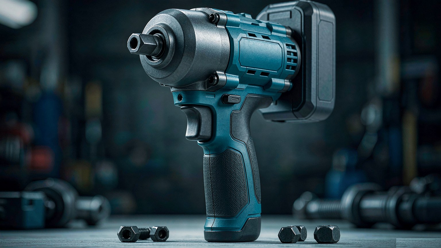
For brushless power tools, most engineers size the MOSFET by bus voltage and motor rated current, then pick a freewheeling or reverse-polarity-protection Schottky from a VF table. The lowest-drop part seems best. But power tools differ from inverters and server supplies: the load is a human hand. Stall, plug/unplug and reverse-polarity transients occur within a ten-centimeter grip radius, while heat dissipation is industry's worst. Module survival depends on three margins hidden by VF tables.
1. Where Schottky Modules Actually Sit in a Power Tool
Set the device boundary: at 18–20 V battery platforms, the three-phase bridge of a brushless drive relies on MOSFET body diodes for freewheeling, and low-voltage discretes cover it. The value of Schottky modules is concentrated in three power-side locations.
First, the secondary output rectification of chargers and fast-charge docks: an industrial multi-bay fast charger can deliver tens of amperes, with secondary rectification switching at tens to hundreds of kilohertz. The reverse recovery loss of silicon fast-recovery diodes is a dominant contributor to charger enclosure temperature rise.
Second, reverse-polarity protection and ORing of paralleled battery packs: at the moment a pack is hot-plugged, the inrush from bus capacitor charging — plus the user's wrong-way insertion — is borne entirely by this path.
Third, the AC-DC front end of high-power benchtop tools (table saws, air compressors, industrial vacuums): PFC output rectification and the bleed path for pumped-up bus energy, at power densities comparable to a variable-frequency drive.
All three locations share one trait: modest steady-state current, frequent transient events, and the smallest thermal margin in the system. That is why "best on the datasheet" so often fails here.
2. Margin One: Stall and Plug-In Surges — Compute the IFSM/IF Ratio First
A brushless angle grinder at stall draws 6–8× its rated current; at the instant a battery pack is hot-plugged, bus capacitor charging inrush is limited only by loop impedance. Both numbers land directly on the Schottky module.
Do not compare IFSM absolute values alone — compare the ratio of IFSM to steady-state rated current IF, the same logic applied in the site's earlier analysis of surge boundaries in domestic replacement. A device with a higher absolute IFSM but also a higher steady-state IF may actually have a tighter relative surge margin. Take Hypersemi's Schottky modules as an example: HS8MBRH200N1X100 (100 V / 200 A, IFSM 1650 A) has a ratio of 8.3×, and HS8MBRH400N1X100 (100 V / 400 A, IFSM 3300 A) also 8.3× — the consistent ratio across the series shows surge capability scaling linearly with die area, while HS11UDA600N1X100 (100 V / 600 A, IFSM 4800 A) sits at 8×. For the repetitive surge duty of power tools — where every stall is another surge event — go one step beyond the IFSM/IF ratio and apply a duty-cycle derating: single-surge energy × stalls per hour is the real thermal stress.
3. Margin Two: In a Hand-Held Device, Every 0.1 V of Drop Is Junction Temperature
The reverse-polarity and ORing path conducts continuously; loss = VF × I × duty cycle, with no switching loss to dilute it. At 20 A continuous: a VF = 1.05 V solution dissipates 21 W, while a VF = 0.75 V solution (e.g., HS8MBRH300N2X100, 200 V / 300 A / VF 0.75 V / IFSM 2000 A) dissipates 15 W.
A 6 W difference, in a battery-pack structure cooled only by natural convection from the enclosure with no heatsink, translates to roughly 15–20°C lower junction temperature. This is exactly where silicon Schottky "trade VF for current density" design earns its keep: the M31H-packaged HS8MBRH series pushes VF down to 0.75–0.95 V, moving the reverse-polarity path from "barely tolerable to the touch" back inside the safe junction-temperature envelope.
4. Margin Three: When Packs Are Paralleled, Silicon Schottky's Negative Temperature Coefficient Is a Trap
Industrial equipment often parallels multiple battery packs for extended capacity, putting the protection Schottky into a naturally paralleled configuration. A common mistake is to carry over the positive-temperature-coefficient self-current-sharing property of SiC Schottky diodes to silicon Schottky: silicon Schottky VF has a negative temperature coefficient, and in parallel operation a "hotter device steals more current" positive feedback can form, with thermal runaway risk. This was derived in full in the site's article "Industrial Power N+1 Redundant Paralleled Silicon Schottky: Can Positive Temperature Coefficient Achieve Self-Current-Sharing?" (see Industrial Power Schottky Module Selection), and the conclusion applies equally to paralleled power-tool packs: each parallel branch must have an explicit current-sharing design (series ballast resistance or per-branch thermal coupling), rather than relying on the device's own temperature behavior.
5. Selection Table
Application Position | Duty Trait | Recommended Part | Key Ratings | Notes |
Charger secondary rectification | High frequency, continuous conduction | 100 V / 200 A / VF 0.95 V / IFSM 1650 A | M31H, non-isolated | |
Reverse-polarity protection + high-power front end | Low VF priority | 200 V / 300 A / VF 0.75 V / IFSM 2000 A | Lowest VF in series | |
Multi-pack parallel ORing | Large repetitive surges | 100 V / 400 A / VF 0.95 V / IFSM 3300 A | M45 package; 600 A/800 A grades also available | |
Isolated mounting | Electrical isolation required | 100 V / 100 A / VF 1.0 V / IFSM 800 A | M01G isolated package |
All 14 modules can be filtered by package (M01G/M31H/M45/M58), isolation, VF, and IFSM on the Schottky Modules product page.
Recommended verification sequence: (1) derate IFSM against the stall-current curve's duty cycle; (2) measure VF on the reverse-polarity path at 25°C and 100°C — do not subtract typical values; (3) run thermal-consistency testing on any paralleled-pack scheme; (4) retest output short-circuit single-event surge on charger designs.
6. Conclusion
The end point of Schottky module selection for power tools is not the lowest VF on a datasheet, but remaining inside the safety boundary under the most frequent transient events: for surges, the IFSM/IF ratio with duty-cycle derating; for reverse-polarity protection, conduction loss at real current and junction temperature; for paralleling, the current-sharing structure rather than the device's temperature characteristic. Only after these three margins are computed does the VF table earn its place in the ranking.
7. FAQ
Q: Why aren't Schottky modules generally used for freewheeling in brushless power tools?
A: At 18–20 V platforms, MOSFET body diodes handle freewheeling; Schottky modules add value in the three power-side positions: charger rectification, battery-pack reverse-polarity protection/ORing, and the AC-DC front end of high-power benchtop tools.
Q: Can reverse-polarity protection Schottky diodes be paralleled for higher current?
A: Yes, but silicon Schottky VF has a negative temperature coefficient, so parallel operation risks a current-stealing positive feedback. Each branch must have an explicit current-sharing design (series ballast resistance or independent thermal coupling); self-current-sharing cannot be assumed from the device's temperature behavior.
Q: Is a bigger IFSM always better?
A: No. Compare the IFSM-to-IF ratio and derate by the frequency of stall/plug-in events. Judging by absolute IFSM alone overestimates the margin.