

Joint Heating in Quadruped Robots: How Schottky Modules Reduce Thermal Losses in Free‑wheeling Paths
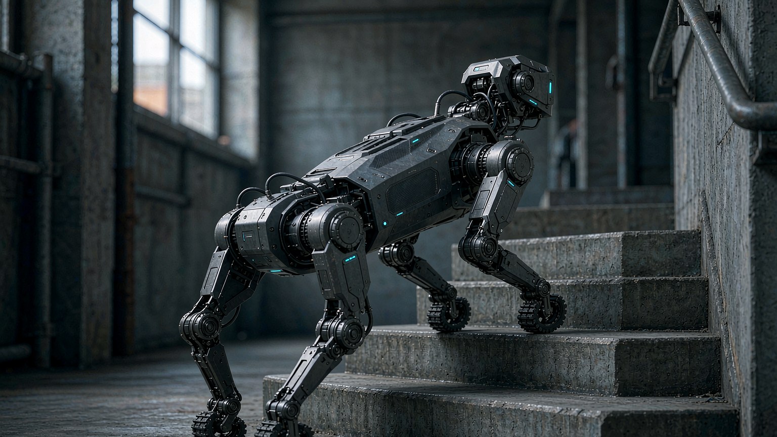
For quadruped robots, drive‑stage losses contribute around 15 % of total joint heat generation. Within drivers, power‑device switching and conduction losses account for 30 %‑60 % of total drive dissipation. Under high‑frequency motor start‑stop and PWM commutation conditions, reverse‑recovery loss and forward‑voltage‑drop loss from the free‑wheeling loop are frequently underestimated heat sources. Hypersemi Schottky modules feature 0.75 V‑class low forward voltage and near‑zero reverse‑recovery
1. Transient Heat Build‑up: Overlooked Losses on Free‑wheeling Path
When a quadruped robot lands after a jump, its joint motor enters generator mode, and regenerative current flows through free‑wheeling diodes. Silicon fast‑recovery diodes produce sharp reverse‑recovery current spikes at each PWM turn‑off. These losses add to MOSFET switching losses. Since joint housings are compact and enclosed, heat cannot dissipate easily and leads to sharp local temperature rise.
Engineering experience shows that a mere 0.4 V forward voltage drop can introduce approximately 12 % system efficiency penalty. High‑dynamic locomotion requires sufficient control bandwidth so switching frequency cannot be arbitrarily reduced, further increasing the proportion of free‑wheeling‑path losses.
2. Heat‑reduction Principle of Schottky Modules: Low Dissipation and Fast Turn‑off for Free‑wheeling Branches
Take HS8MBRH200N2X100 as an example: 200 V blocking voltage, 200 A continuous forward current, 1 V forward voltage, 1650 A surge current in M31H package. Full datasheet: https://www.hypersemi.com.cn/cn/products/schottky‑modules/HS8MBRH200N2X100.html. SiC Schottky diodes operate via majority‑carrier conduction without minority‑carrier storage effects. During turn‑off, only minor junction‑capacitance discharge current occurs, practically eliminating the reverse‑recovery loss spikes typical for silicon fast‑recovery diodes. For joint drivers with frequent commutation, this reduces heat generated per switching cycle.
For higher‑current joint‑drive requirements, the pin‑compatible HS8MBRH400N2X100 (400 A / 200 V / 0.95 V / IFSM 3300 A, M31H) offers higher current capability without changing PCB footprint. Selection of main‑switch MOSFETs also impacts overall driver heating. Hypersemi MOSFET product page: https://www.hypersemi.com.cn/cn/products/mosfets. Designers can filter MOSFETs with matching voltage, current and package footprint to build a complete power solution combining “low‑loss main switches + low‑loss free‑wheeling devices”.
3. Engineering Selection Notes
1. Schottky modules only mitigate free‑wheeling‑loop losses. Full joint‑temperature improvement needs co‑optimization of MOSFETs, drive parameters and mechanical thermal design; diodes alone cannot achieve full thermal performance targets.
2. Under highly dynamic shock conditions (jumping, emergency stops), carefully verify device surge‑current ratings to accommodate peak regenerative current.
3. All device parameters and datasheets shall follow official releases on the Hypersemi website.