

Hot-Swap ORing: The Irreplaceable Role and Real Cost of Schottky Modules
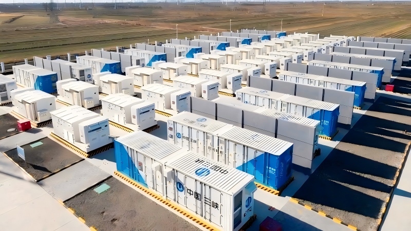
Hot swapping requires that the load remain powered when a battery cluster is replaced. The ORing diode must operate passively under the logic of “the higher voltage conducts, the lower voltage blocks,” without relying on a controller, without requiring gate drive, and with a simple failure mode. This is the core reason Schottky diodes are still widely used in battery cluster ORing.
The cost is continuous conduction loss. For a 200A branch with VF=0.75V, the dissipation of a single device is approximately 150W. The engineering significance of a Schottky module is that it moves this 150W from an “uncontrollable hotspot inside the chip” to standardized package baseplates such as M31H/M45/M58, giving thermal design a documented basis. However, the module does not reduce the absolute loss—it only turns thermal management from “experience-based” into “calculable.”
100–200V / 200–800A: When should a Schottky module be used, and when must the design be changed?
Boundaries suitable for using a module: battery cluster voltage platform ≤100Vdc (VRRM 100–200V leaves margin); single-branch continuous current ≥150A; the cabinet has forced air cooling or a cold-plate heat conduction path; the system accepts a “fixed VF drop” as an inherent cost of ORing.
Boundaries at which the design should be switched: bus voltage > 200V (silicon Schottky reverse leakage rises exponentially with temperature, and the VRRM upper limit and leakage characteristics are no longer controllable); pursuit of ultimate efficiency (the loss advantage of ideal diodes + MOSFETs in current ranges above 10A expands by orders of magnitude); fully enclosed space with no directional heat dissipation path.
A pragmatic compromise strategy is: use modules on the battery cluster output side to handle reverse-polarity protection and ORing, while retaining low-VF SMD Schottky diodes or ideal diodes for the multiple auxiliary power ORing inside the BMS control board, so that modules and SMD devices each operate in current ranges matched to their thermal resistance.
Model matching for Hypersemi Schottky modules in this scenario
HS8MBRH300N2X100 (200V / 300A / VF typ. 0.75V / IFSM 2000A, M31H, Non-isolation SBD): a VF of 0.75V is relatively low in the 200V/300A class, matching a battery cluster hot-swap branch with continuous current of 200–250A and surge from the moment of inter-cluster connection. The 2000A IFSM covers the bus capacitor charging surge when a single cluster is connected, not short-circuit current-level events.
HS13MBS200N1X100 (100V / 200A / VF typ. 0.95V / IFSM 1650A, M58, Isolation SBD): the isolated package reduces the interference risk caused by common-mode potential differences on the baseplate when multiple clusters are paralleled, making it suitable for battery rack installation scenarios with explicit insulation coordination requirements. The slightly higher VF than the non-isolated version is the engineering cost of obtaining isolation characteristics.
HS11UDA800N1X100 (100V / 800A / VF 0.95V / IFSM 6400A, M45, Non-isolation SBD): the 800A rated current and 6400A surge capability correspond not to the continuous operating current of a single cluster, but to the parallel bus side of multiple clusters—when one cluster has a short-circuit fault, the surge current fed into the fault point by the other clusters must be withstood by the bus protection device. At this position, the weighting of IFSM is higher than that of VF.