

Single-Phase String PV Inverters: Achieving Both No-Derating at High Temperature and High Low-Light Efficiency
Generation revenue for a residential PV inverter depends more on whether it avoids derating during the hottest hours and can still generate under the weakest sunlight. The HG75T65L
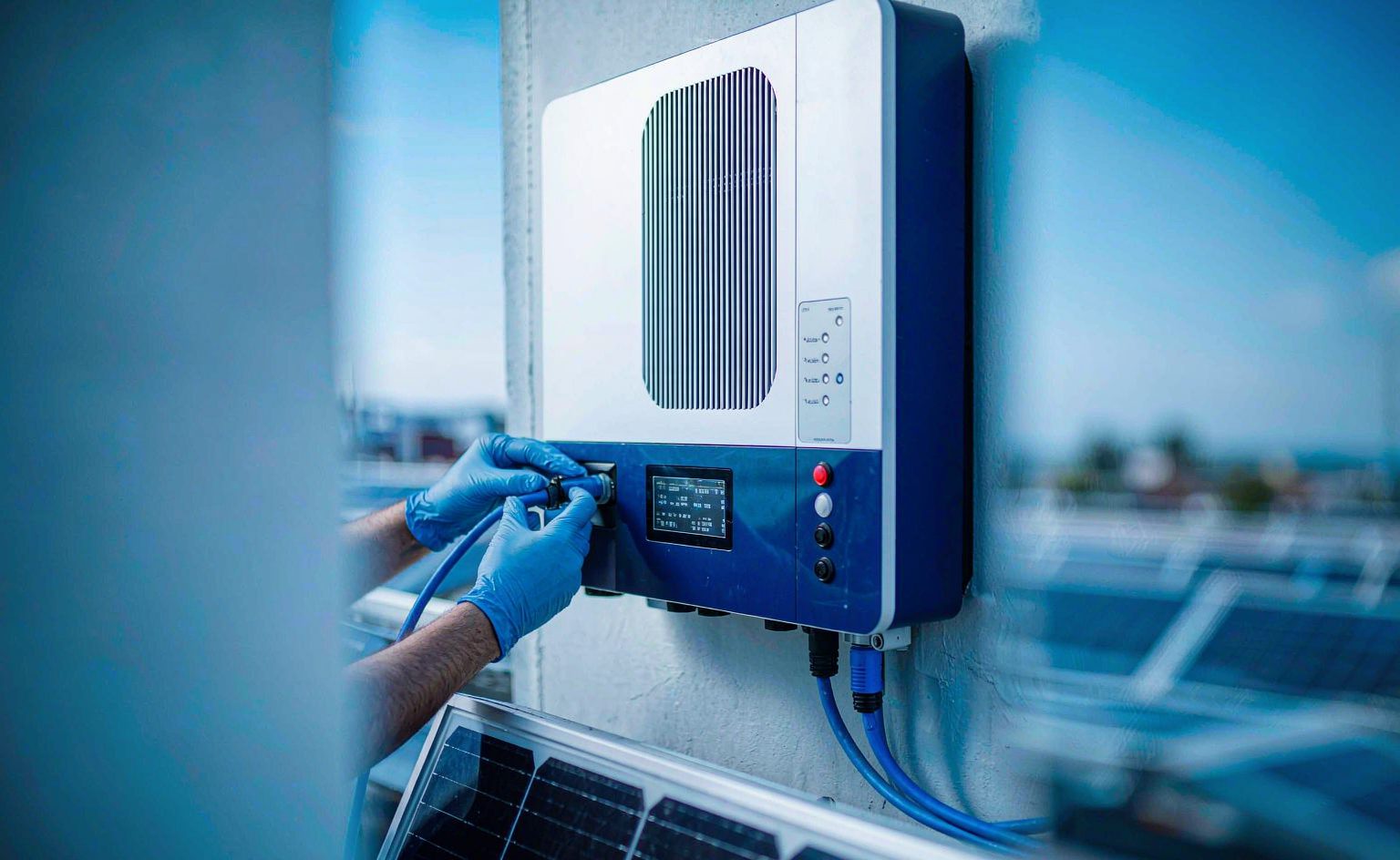
Generation revenue for a residential PV inverter depends more on whether it avoids derating during the hottest hours and can still generate under the weakest sunlight. The HG75T65LX100s 175C junction capability and 1.8V saturation voltage target exactly those two points.
Bottom Line First: The Selection Boundary for a 15kW Residential PV Inverter
If your inverter meets the conditions below, a 650V / 75A IGBT discrete such as the HG75T65LX100 is a high-confidence choice:
- Rated power within 15kW — the mainstream range for single-phase string inverters
- Heatsink temperature sitting above 85℃ for long periods — with outdoor installation and natural convection, summer case temperatures easily exceed this
- Switching frequency around 16kHz — the common operating point balancing inductor size against switching loss
Conversely, for a three-phase string or central inverter above 30kW, go directly to a 34mm or 62mm module solution. Discretes cannot cover the current and thermal requirements.
Three Real Pain Points in Single-Phase String Inverters
Design conflicts in residential PV inverters concentrate in three areas:
- High-temperature derating eats generation revenue. Conventional IGBTs must derate once the heatsink exceeds 85℃, directly reducing PV array utilization. For the owner, that is real lost generation.
- Low-light efficiency collapse. Below 400W/m² irradiance (early morning, evening, overcast), conduction loss exceeds 50% of total loss, so device saturation voltage determines whether the inverter can still generate at all.
- The cooling system consumes weight and cost. Cooling often accounts for more than 30% of total unit weight, raising installation cost and constraining mounting options.
The HG75T65LX100 was designed against exactly these three issues.
Five Key Characteristics of the HG75T65LX100
1. 175℃ Junction Temperature: The Engineering Value of No Derating
Maximum junction temperature of 175℃, 25℃ above a conventional 150℃ device. The practical value: full 15kW output sustained at 50℃ ambient with no derating. For an outdoor-mounted inverter, that translates directly into generation revenue.
Thermal resistance is Rth(j-c) = 0.28K/W, allowing heatsink volume to shrink by roughly 60% and making natural convection viable within an 85℃ base-plate limit.
2. Saturation Voltage: 1.8V @75A (175℃)
Trench-gate field-stop technology with an optimized process delivers very low saturation voltage. At 175℃, saturation voltage is just 1.8V at 75A.
This parameter matters most under low-light conditions: at IC=15A, conduction loss is only about 0.288W (Pcon = IC × VCE(sat)). The lower the loss, the longer the window in which the inverter can still generate during morning and evening hours.
3. Balance Between Conduction and Turn-Off Loss
This is an N-channel trench-gate field-stop IGBT whose process optimization strikes a good balance between conduction loss and turn-off loss (Eoff). In hard-switched topologies, that balance point directly shapes the overall efficiency curve.
4. Integrated Fast-Recovery Diode: VF = 1.4V at 175℃
The built-in fast-recovery diode has a forward drop of 1.4V at 175℃, improving freewheeling efficiency by about 18%. Diode loss is a significant share of total loss during the freewheeling phase, so optimizing this parameter shows up directly in overall efficiency.
5. Dynamic Capability: 300A Pulsed / 16kHz
Pulsed current capability of 300A handles events such as string PID recovery surges. Switching frequency supports 16kHz, allowing roughly 30% inductor size reduction versus lower-frequency designs.
Key Parameters at a Glance
| Parameter | Value | Test Condition |
|---|---|---|
| Blocking voltage VCES | 650V | — |
| Continuous current IC | 75A | TC=100℃ |
| Pulsed current ICM | 300A | — |
| Saturation voltage VCE(sat) | 1.8V | 75A / 175℃ |
| Thermal resistance Rth(j-c) | 0.28K/W | — |
| Maximum junction temperature Tj,max | 175℃ | Continuous |
| High-temperature switching loss Ets | 7.5mJ | High temperature |
| Diode forward voltage VF | 1.4V | 175℃ |
| Switching frequency support | 16kHz | — |
| Package | TO-3PN | |
Application Case: 15kW Residential Single-Phase String Inverter
Design targets: no derating at 50℃ ambient, sustained generation under low light, natural convection to control cost.
Measured results:
- Full 15kW output with no derating at 50℃ ambient
- Heatsink volume reduced roughly 60%, with natural convection holding base-plate temperature ≤ 85℃
- Average daily gain of about 2.3kWh at 300W/m² irradiance (efficiency 98.1% → 98.7%)
- Normal operation under string PID recovery surges (covered by 300A pulsed capability)
The "2.3kWh extra under low light" figure is the most telling: the gain comes not from peak efficiency but from very low conduction loss at low current. A PV inverter operates in the low-irradiance range for most of the day, and efficiency improvements there often contribute more to annual yield than peak efficiency does.
Two Points Most Often Overlooked During Selection
1. Low-Light Efficiency Matters More to Annual Yield Than Peak Efficiency
The "peak efficiency" on a module nameplate is usually measured under standard test conditions (1000W/m², 25℃), but inverters actually operate in the 200–600W/m² range most of the time. Ask suppliers for the efficiency curve at low current rather than relying on a single peak figure. Devices with low saturation voltage at low current hold a clear advantage in that range.
2. "No Derating at High Temperature" Must Be Verified Against Measured Junction Temperature
A "175℃ junction" rating is the device's tolerance ceiling, not a permitted long-term operating point. The correct method: calculate steady-state junction temperature from actual cooling conditions, confirm it stays under 125℃ with margin. The real value of 175℃ is providing buffer for extreme conditions (summer afternoons, dust-clogged heatsinks), not serving as a normal operating point.
Frequently Asked Questions
Which devices can the HG75T65LX100 replace?
It serves as a replacement option for devices such as FGH60N60SM_F085, suited to single-phase string PV inverters, high-frequency automotive sine-wave AC220V inverters, PV inverters, outdoor energy-storage power supplies, UPS systems, variable-frequency drives, welding machines, and industrial sewing machines — all hard-switched applications. Verify gate drive voltage range and switching timing requirements before substitution to ensure driver compatibility.
Why is a 650V rating right for a single-phase string inverter?
Single-phase string inverters typically run a DC bus around 400V (corresponding to 220V single-phase AC output). Adding switching spikes and grid-fluctuation margin, a 650V device is the mainstream choice. If the system uses a higher DC bus (such as an 800V bus in three-phase designs), select a 1200V-class device instead. The selection principle: bus voltage × 1.5 or greater as the blocking-voltage threshold.
How much generation is lost to dust on the heatsink?
More than most people expect. Dust accumulation significantly raises thermal resistance, so junction temperature climbs at the same loss level. If the device lacks high-temperature headroom, the inverter self-derates during hot afternoon hours — losing precisely the hours with the highest generation of the day. Choosing a device with ample high-temperature margin (175℃ class) maintains output even as heatsink performance degrades, an easily underestimated reliability benefit for outdoor applications.
Summary
The HG75T65LX100 is positioned as an IGBT discrete solution for single-phase string PV inverters up to 15kW, delivering no derating at high temperature and high efficiency under low light. Its value is not a few tenths of a point of peak efficiency but the combination of 175℃ junction margin, low saturation voltage, and low diode forward drop — letting the inverter generate as much as possible during the hottest hours and the weakest sunlight.
Need an efficiency study for a specific model? Tell us your rated power, bus voltage, and cooling method, and we will recommend a matching device combination.