

Selecting a Lithium Battery Protection Circuit: The Value and Limits of Dual-N-Channel Co-Packaged MOSFETs
A dual-N-channel co-packaged MOSFET such as the 8205 family, paired with a protection IC, integrates bidirectional cutoff plus over-discharge and overcurrent protection into an ext
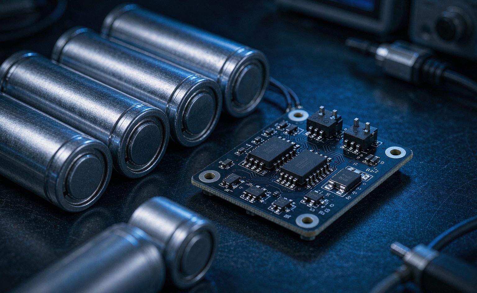
A dual-N-channel co-packaged MOSFET such as the 8205 family, paired with a protection IC, integrates bidirectional cutoff plus over-discharge and overcurrent protection into an extremely small package for single- and dual-cell applications. This article defines where its capability limits lie.
Bottom Line First: What Devices Belong in a Lithium Battery Protection Circuit?
If your product meets the conditions below, a dual-N-channel co-packaged MOSFET such as the 8205 family paired with a protection IC is the mainstream choice today:
- Single- or dual-cell lithium battery — electric toothbrushes, power banks, Bluetooth earbuds, portable appliances
- Discharge current within 6A — the typical capability range for TSSOP-8 / SOT-23-6L packaged devices
- Both cost and size are sensitive — consumer products impose hard constraints on BOM cost and PCB area
Conversely, for multi-series traction packs (EVs, energy storage), you need discrete power MOSFETs plus a dedicated BMS IC. Integrated protection solutions like the 8205 fall well short on current capability.
Three Real Pain Points in Lithium Battery Protection Circuits
Design conflicts in consumer lithium-battery products concentrate in three areas:
- The safety-versus-cost conflict. Protection must be complete (overcharge, over-discharge, overcurrent, short circuit), yet consumer products face extreme BOM cost pressure and cannot afford extra components.
- Standby current eats into runtime. The protection circuit is permanently online, so on-resistance and quiescent current draw directly on battery capacity. Users perceive it as "it loses charge even when I am not using it".
- Space is compressed to the limit. In products like power banks and toothbrushes, the protection board is often no larger than a fingernail.
The value of the 8205 family of co-packaged MOSFETs is precisely that it offers a sufficiently integrated solution within these three constraints.
Core Characteristics of the Typical Solution
1. Integrated Dual N-Channel: One Device for Bidirectional Cutoff
Typical ratings are 20V blocking, 6A continuous in a TSSOP-8 or SOT-23-6L package. Two N-channel MOSFETs are integrated in a single package, with a back-to-back configuration enabling bidirectional cutoff of the charge and discharge paths — eliminating the routing and board area of discrete solutions.
2. Ultra-Low On-Resistance: RDS(on) in the 28mΩ Range
On-resistance directly determines energy loss in both standby and operating states. Low RDS(on) means less energy wasted in the protection loop — a hard requirement for runtime-sensitive portable devices.
Note that these two devices sit in series in the charge/discharge path, so total loop resistance is roughly twice the single-device value (or higher). The lower the per-device RDS(on), the greater the overall benefit.
3. Protection Functions: Over-Discharge, Overcurrent, Short Circuit
Working with a protection IC (such as the DW01 family), the device forms a complete lithium battery protection circuit:
- Over-discharge protection (ODP) — automatically cuts the discharge path when battery voltage falls below a preset threshold, preventing irreversible damage from deep discharge
- Overcurrent protection (OCP) — monitors charge/discharge current in real time, shutting off immediately when the safe threshold is exceeded, preventing overload and short-circuit damage
- Short-circuit protection — interrupts the loop within microseconds when the load short-circuits
4. High-Accuracy Voltage Monitoring: ±1%
Working with the protection IC, voltage monitoring accuracy reaches ±1%, preventing voltage from falling below 3.0V (threshold customizable) and ensuring a consistent discharge cutoff point. For paralleled cell groups, this accuracy directly determines cell-to-cell consistency.
5. Package and Thermal Performance
TSSOP-8 / SOT-23-6L packages are compact and cost-effective, suited to miniaturized designs. Fast switching supports high-frequency operation with low power consumption.
Key Parameters at a Glance
| Parameter | Value | Notes |
|---|---|---|
| Blocking voltage VDS | 20V | Suited to single/dual-cell lithium batteries |
| Continuous current ID | 6A | — |
| On-resistance RDS(on) | ~28mΩ | Per device; loop has two in series |
| Channel type | Dual N-channel | Back-to-back bidirectional cutoff |
| Voltage monitoring accuracy | ±1% | With protection IC |
| Over-discharge threshold | 3.0V (customizable) | Prevents deep discharge |
| Package | TSSOP-8 / SOT-23-6L | Compact surface mount |
Typical Application Scenarios
Power Banks (Portable Chargers)
The core benefit is extended battery life: ultra-low RDS(on) significantly reduces energy loss, raising cycle life from the typical 500 cycles to over 800.
Performance features include smart load detection (auto-cutoff when no device is connected), fast-charging support (5V/3A input without noticeable voltage drop), and thermal safety (preventing overheating during wireless charging). For users, the direct benefit is longer runtime per charge and better long-term reliability.
Electric Toothbrushes
The technical advantage is precision voltage monitoring (±1% accuracy) preventing voltage from dropping below 3.0V, ensuring consistent brush-motor performance. Protection features include waterproof-design compatibility (IPX7-class solutions) and instantaneous short-circuit protection.
Other Applications
- Bluetooth earbuds and wearables — small-capacity batteries with extreme demands on protection-board size
- Portable appliances — hand-held fans, mini vacuums
- Personal care devices — requiring fast short-circuit protection response
Three Common Selection Pitfalls
1. Calculating On-Resistance for a Single Device Only, Ignoring the Series Pair
This is the most common error. Two devices in series in the charge/discharge loop mean total on-resistance is roughly twice the single-device value. Estimating loss from a single-device figure underestimates actual heat generation by half. Calculate total loop loss as "single RDS(on) × 2 × I²".
2. Ignoring On-Resistance Temperature Drift
MOSFET RDS(on) has a positive temperature coefficient — typically rising more than 50% from 25℃ to 125℃ junction temperature. Device temperature rises noticeably under high discharge current, making actual loop loss far higher than a room-temperature calculation suggests. Look up RDS(on) at the maximum operating temperature.
3. Underestimating Protection-IC-to-MOSFET Matching Requirements
Protection thresholds, response time, and gate drive capability must all match. If the MOSFET's gate threshold voltage does not match the protection IC's drive voltage, protection may act unreliably — either failing to disconnect when it should, or triggering falsely. Verify gate drive specifications for both, and reference proven combinations.
Frequently Asked Questions
Why use dual N-channel rather than a single MOSFET for protection?
Because of the unidirectional conduction of the body diode. After a single MOSFET turns off, its body diode still provides a reverse path, so current cannot truly be interrupted. With two N-channel MOSFETs back-to-back, one body diode is always reverse-biased regardless of current direction, achieving genuine bidirectional cutoff. This is both the foundation for independently controlling overcharge and over-discharge protection and the reason dual-N-channel integrated packages exist.
How does the 8205 family relate to the co-packaged MOSFET product line?
The 8205 family is itself a form of co-packaged MOSFET — two N-channel MOSFETs integrated in a single package. The broader co-packaged MOSFET category also includes N+P combinations for motor forward/reverse drive. Selection hinges on whether the application needs "bidirectional cutoff" or "forward/reverse control" — dual N-channel for the former, N+P for the latter.
How do I verify that a protection scheme is truly reliable?
Validate from three angles. First, short-circuit response time — measure the total time from load short circuit to loop interruption, confirming it meets specification. Second, batch consistency of the over-discharge threshold — sample multiple production lots and measure cutoff voltage to check whether spread falls within the promised ±1%. Third, long-term standby consumption — leave a fully charged battery idle and measure voltage decay to confirm the protection circuit's quiescent loss is acceptable.
Summary
Selection logic for lithium battery protection circuits is straightforward: trade integration for cost and size, and low on-resistance for runtime. In single/dual-cell small-capacity applications, a dual-N-channel co-packaged MOSFET such as the 8205 family working with a protection IC integrates bidirectional cutoff, over-discharge protection, and overcurrent protection into an extremely small package — currently the best-balanced solution for consumer products that are acutely sensitive to both space and cost.
Need a protection-scheme selection study for a specific product? Tell us your battery specification, discharge current, and size constraints, and we will recommend a matching device combination.