

How Co-Packaged MOSFETs Improve Cordless Power Tool Runtime and Control Response
The runtime bottleneck in cordless tools often comes down to conduction loss. A 30V-class N+P co-packaged MOSFET such as the HM8324F4X100 trades 14mOhm-class on-resistance and 11.1
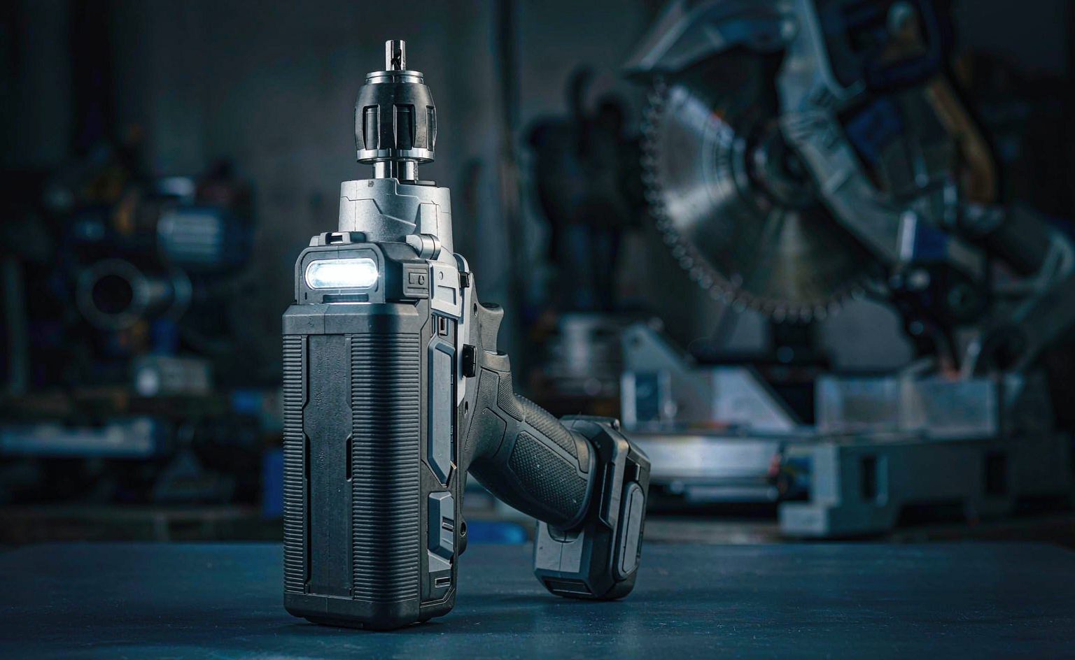
The runtime bottleneck in cordless tools often comes down to conduction loss. A 30V-class N+P co-packaged MOSFET such as the HM8324F4X100 trades 14mOhm-class on-resistance and 11.1ns switching for longer runtime and more responsive control.
Bottom Line First: Where Does a Cordless Tool's Runtime Bottleneck Actually Sit?
If your power tool meets the conditions below, moving to a low-on-resistance co-packaged MOSFET is the most direct upgrade available:
- Battery powered, with runtime per charge as a headline selling point — every 10% reduction in conduction loss buys 10% more runtime
- Frequent stall events — drilling, cutting, and bolt-driving all stall, with transient current reaching 3–5× rated value
- Housing temperature is a user-experience pain point — users notice housing above 45℃ immediately on a hand-held tool
Conversely, for a corded tool with no speed control, device conduction loss has limited impact on user experience. Prioritize cost and reliability, and do not pay extra for ultra-low on-resistance.
Three Real Pain Points in Brushless Power Tools
Engineers working on power-tool electronics eventually hit the same cluster of problems:
- Startup lag makes the tool feel weak. Slow switching means torque does not build at the instant the trigger is pulled — users perceive it directly as "soft".
- Speed droop under heavy load. During sustained trigger pressure, device temperature rises, on-resistance rises with it, and output power falls — producing a "the harder I push, the weaker it gets" experience.
- Runtime anxiety. Conduction loss eats battery capacity directly. With the same 2.0Ah pack, a 5-percentage-point difference in drive efficiency means a dozen fewer holes the user can actually drill.
The common solution to all three is lower conduction loss per ampere plus faster switching response.
Five Key Characteristics of Co-Packaged MOSFETs
1. On-Resistance Is the Primary Variable for Runtime
In a 30V-class N+P co-packaged MOSFET (such as the HM8324F4X100 family), N-channel on-resistance reaches the 14mΩ @10V range and P-channel about 29mΩ @10V. Against conventional solutions above the 6.5mΩ class, conduction loss drops noticeably at equal current.
Put that in context: at 40A continuous, per-device dissipation typically differs by 4W to 10W — heat that ultimately has to be removed by the heatsink or the housing.
2. Switching Speed Determines "Trigger Feel"
N-channel turn-on delay is td(on) = 11.1ns with fall time tf = 3.6ns. The faster the switching, the more responsive the PWM duty cycle, and the shorter the delay from trigger pull to speed build-up.
Commutation dead time can be compressed from the industry-typical 100ns to the 35ns range, which directly improves torque ripple at low speed.
3. Support for PWM Above 20kHz
Gate charge of Qg = 12nC keeps switching loss low and supports PWM frequencies above 20kHz. Pushing the switching frequency past 20kHz essentially eliminates audible motor whine — that is how "quiet" is achieved at the electronics level.
4. Thermal Management: TO-252 Surface-Mount
The TO-252 package supports surface mounting and saves PCB area. Thermal resistance is about 4.6℃/W (P-channel) with a 150℃ maximum junction temperature, sufficient to pass motor stall testing.
5. Reliability: 50A Pulsed Capability
Pulsed current capability of 50A handles startup surges and stall transients. The integrated body diode provides a freewheeling path; the shorter the reverse recovery time trr, the lower the freewheeling-loop loss, contributing directly to overall efficiency.
Key Parameters at a Glance
| Parameter | N-Channel | P-Channel |
|---|---|---|
| Voltage rating VDS | 30V | -30V |
| Continuous current ID | 18A | -14A |
| On-resistance RDS(on) | 14mΩ @10V | 29mΩ @10V |
| Turn-on delay td(on) | 11.1ns | — |
| Fall time tf | 3.6ns | — |
| Gate charge Qg | 12nC | — |
| Pulsed current IDM | 50A | — |
| Maximum junction temperature Tj,max | 150℃ | 150℃ |
| Thermal resistance Rth(j-c) | — | 4.6℃/W |
| Package | TO-252 (surface mount) | |
Application Case: 18V Brushless Drill Drive Retrofit
Design targets: faster startup response, more holes per charge, controlled housing temperature rise.
Measured results:
- No-load acceleration to peak RPM in 0.18 seconds (comparison solutions typically > 0.3s)
- Per-device dissipation of about 4.8W at 40A continuous (conventional solutions ≥ 10.4W)
- With a 2.5℃/W thermal path, full-load housing temperature rise ≤ 39℃, allowing 60% reduction in heatsink volume
- More than 100 continuous Φ5mm × 10mm deep holes per charge on a 2.0Ah pack
Cold-start behavior deserves separate mention: at -25℃, a device with low threshold voltage (VGS(th) in the 2V range) still retains about 98% of its torque output, solving the familiar "soft start in cold weather" problem for power tools.
Two Points Most Often Overlooked During Selection
1. Verify On-Resistance at Operating Junction Temperature, Not Room Temperature
MOSFET on-resistance has a positive temperature coefficient — from 25℃ to 125℃ junction temperature, RDS(on) typically rises more than 50%. Selecting on the room-temperature nominal figure severely underestimates losses at the actual operating point. The correct approach is to look up RDS(on) at the expected maximum junction temperature, then calculate loss and temperature rise, closing the loop iteratively.
2. Watch Switching-Timing Symmetry with N+P Co-Packaged Devices
N-channel and P-channel switching speeds differ inherently (P-channel is usually slower). If the drive circuit uses symmetric gate resistors, the high-side and low-side timings will mismatch, showing up as current spikes at commutation. Adjust the N-channel and P-channel gate resistors separately and measure the commutation waveform.
Frequently Asked Questions
Why use an N+P co-packaged device instead of two discrete MOSFETs?
Three main reasons: first, PCB area — a co-packaged device occupies far less board space, which matters in a compact hand-held tool; second, parasitic consistency — the two dies inside one package are closer in thermal coupling and parasitic inductance, making commutation behavior more predictable; third, assembly efficiency — one component replaces two, improving both placement throughput and yield.
Is a 30V rating sufficient?
For 18V and 24V battery systems, 30V is the mainstream choice. A fully charged pack sits around 21V (18V system) or 29V (24V system); adding the commutation voltage spike, a 30V device has ample margin in an 18V system. For 24V systems, verify the spike amplitude before deciding, and step up to the 40V class if necessary.
How do I know whether an efficiency improvement is real?
The most reliable method is to measure "work completed per charge" rather than relying on bench efficiency figures alone. Run the tool under constant load and record cumulative work (holes drilled, length cut) from full charge to protection cutoff. This single metric captures conduction loss, switching loss, and thermal derating together.
Summary
The value of co-packaged MOSFETs in power tools is clear: trade lower on-resistance for longer runtime, and faster switching for more responsive control. The milliohm differences on the datasheet ultimately show up as the number of holes in the user's hand and the temperature of the housing — and that is the real battleground in power-tool competition.
Need a drive-stage selection study for a specific tool? Tell us your battery voltage, continuous current, and thermal conditions, and we will recommend a matching device combination.