

HGF200MA120X100 IGBT Module: An Efficiency Solution for Industrial Drives and High-Frequency Power Supplies
For industrial drives and high-frequency power supplies above an 800V bus, at 10-30kHz switching, with constrained cooling, the HGF200MA120X100 balances efficiency against volume v
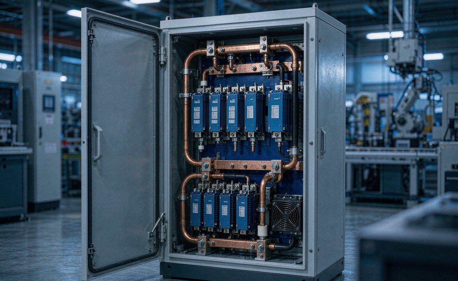
For industrial drives and high-frequency power supplies above an 800V bus, at 10-30kHz switching, with constrained cooling, the HGF200MA120X100 balances efficiency against volume via 28nH module stray inductance and a flat loss-versus-temperature curve.
Bottom Line First: When Should You Choose the HGF200MA120X100?
If your design meets all three conditions below, the HGF200MA120X100 is a high-confidence choice:
- DC bus voltage above 800V — the module is rated 1200V, leaving a margin above 33%
- Switching frequency of 10–30kHz — system efficiency stays above 99% even at 20kHz
- Constrained thermal budget — natural convection or compact forced-air cooling only
Conversely, if your switching frequency is below 6kHz and you have ample heatsink space, a standard planar-gate IGBT module offers better cost-performance. There is no reason to pay for high-frequency capability you will never use.
Three Real Pain Points in Industrial Drives and High-Frequency Power Supplies
Industrial frequency converters, renewable-energy inverter systems, and high-frequency power supplies all stall on the same set of trade-offs during design:
- Switching losses drive up temperature rise, which drives up cooling cost. Every 1% drop in efficiency typically forces a 15% or greater increase in heatsink volume.
- Power-density targets conflict with device footprint. When cabinet space is fixed, device volume becomes the hard ceiling on output capability.
- Parameter drift at elevated temperature makes service life unpredictable. Every 10℃ rise in junction temperature roughly halves device lifetime.
The common solution to all three is the same: reduce loss per ampere while improving heat transfer. The HGF200MA120X100 was designed around exactly that principle.
Five Key Technical Characteristics
1. Switching Losses: Eon 11.5mJ / Eoff 13.9mJ
Built on high-speed Planar-FS (planar-gate field-stop) IGBT technology paired with a fast-recovery diode, the module delivers roughly 40% lower switching loss than conventional solutions (typical @150℃).
Module stray inductance is just 28nH — the critical factor for suppressing high-frequency oscillation. Every 10nH reduction in stray inductance cuts the turn-off voltage spike by roughly 15% under equal conditions, which allows a smaller or simpler snubber circuit.
2. High-Temperature Stability: Continuous Operation at 150℃
Saturation voltage drift is held within 0.2V from 25℃ to 150℃ (measured). This means conduction losses do not deteriorate sharply at elevated temperature. A positive temperature coefficient ensures automatic current sharing when multiple chips are paralleled, preventing any single die from overloading.
3. Power Density: 5.9A/cm³
Standard 34mm package (94 × 34 × 30.2mm) rated for 200A continuous, weighing 160g. Compared with legacy packages of equivalent rating, the footprint shrinks by roughly 30% — a direct gain for compact cabinet designs.
4. Gate Drive Compatibility
An integrated 5Ω gate resistor supports a wide ±20V gate voltage range, with gate charge of only 1.2µC. Low gate charge translates into proportionally lower drive-circuit power dissipation and heat, enabling a simpler and less expensive gate driver design.
5. Safety Margins
1200V / 800A short-circuit withstand capability (10µs), 2500V isolation voltage (AC RMS), and a high creepage design with CTI > 200. Ample margin for the voltage spikes and pollution degrees typical of industrial environments.
Key Parameters at a Glance
| Parameter | Value | Test Condition |
|---|---|---|
| Collector-emitter voltage VCES | 1200V | — |
| Continuous collector current IC | 200A | TC=100℃ |
| Turn-on loss Eon | 11.5mJ | 150℃ |
| Turn-off loss Eoff | 13.9mJ | 150℃ |
| Module stray inductance Ls | 28nH | — |
| Saturation voltage drift | < 0.2V | 25℃ → 150℃ |
| Maximum junction temperature Tj,max | 150℃ | Continuous |
| Short-circuit withstand | 800A / 10µs | 1200V |
| Isolation voltage | 2500V | AC RMS |
| Package dimensions | 94 × 34 × 30.2mm | 34mm standard |
| Weight | 160g | — |
Application Case: 1500V / 100kW String PV Inverter
Design targets: switching frequency ≥ 20kHz, 30% smaller footprint than the previous generation, full-load operation in outdoor high-temperature conditions.
Implementation: two modules in parallel.
Measured results:
- System peak efficiency 99.2% (up 0.7 percentage points over the previous generation)
- Module thermal resistance 0.15K/W (IGBT portion), heatsink volume reduced by 40%
- Power stage footprint reduced 35%, meeting the compact cabinet requirement
- 6000 hours of continuous full-load operation at 45℃ ambient with zero failures
One detail deserves separate mention: the flatness of the switching-loss-versus-temperature curve. Eon at 150℃ is only 47% higher than at 25℃, whereas conventional devices typically show a ratio of 80% to 120%. This is the fundamental reason it maintains stable efficiency under high-temperature, high-frequency operation.
Two Points Most Often Overlooked During Selection
1. Do Not Evaluate on Room-Temperature Data Alone
Most IGBT datasheets specify parameters at 25℃. Industrial drives typically run at case temperatures of 70–90℃ year-round, so losses must be verified at the 150℃ condition. Otherwise the thermal design ends up either over-conservative or inadequate. The HGF200MA120X100's flat loss-versus-temperature curve is designed precisely for this scenario.
2. Stray Inductance Determines Whether You Can Exceed 20kHz
The higher the switching frequency, the greater the di/dt, and the more severe the voltage spike caused by stray inductance. A module-level stray inductance of 28nH means you can substantially simplify or even eliminate the snubber above 20kHz — a direct saving in both cost and volume.
Frequently Asked Questions
Can a 1700V device be used instead?
Technically yes, but it is not recommended. A 1700V device typically has higher conduction drop and switching loss than a 1200V device, so in a system with a bus below 1500V it amounts to deliberate derating at the cost of efficiency. Consider stepping up the voltage class only when the bus exceeds 1100V and significant voltage spikes are present.
Do paralleled modules need current-sharing measures?
The module's positive temperature coefficient means current naturally shifts toward the cooler die, providing inherent current sharing. Even so, we recommend separate gate drive routing and a symmetric power loop layout to avoid introducing artificial imbalance.
How much current can be handled with natural convection?
It depends on ambient temperature and heatsink thermal resistance. Based on a module thermal resistance of 0.15K/W, at 40℃ ambient with a 1.0K/W heatsink, natural convection supports roughly 60–70A continuously. For the full 200A, forced air or liquid cooling is recommended.
Summary
The HGF200MA120X100 has a clearly defined role: to provide a balance point between loss and volume for high-temperature, high-frequency, space-constrained power conversion. Its core advantage is not a peak single-parameter figure but an engineering property — a flat loss curve at elevated temperature. That is precisely the real threshold for long-term reliable operation of industrial equipment.
Need a selection assessment for a specific topology? Tell us your bus voltage, switching frequency, and cooling conditions, and we will recommend a matching device combination.