

BLDC Drive for Quiet Fans: Solving Noise at the Electronics Level
Fan noise does not come from blades and bearings alone. Pushing PWM above 20kHz and compressing switching time and commutation dead time is how electromagnetic whine is eliminated
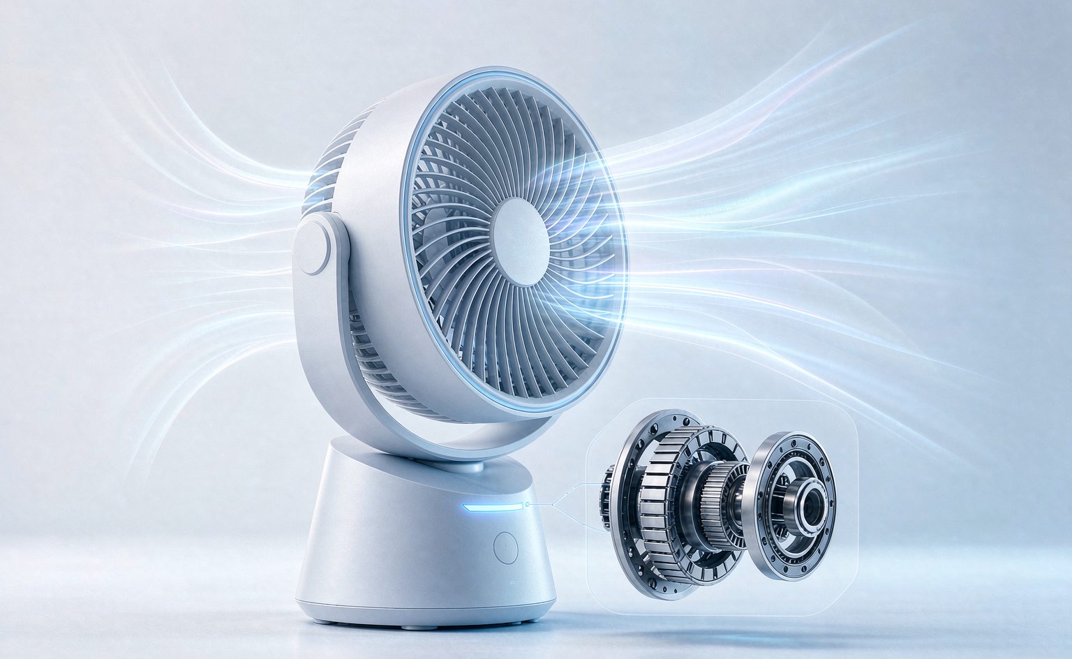
Fan noise does not come from blades and bearings alone. Pushing PWM above 20kHz and compressing switching time and commutation dead time is how electromagnetic whine is eliminated at the drive level - and how N+P co-packaged devices such as the HM8324F4X100 deliver it.
Bottom Line First: Where Should Fan Noise Actually Be Solved?
If your fan product meets the conditions below, improving the motor drive device is the highest return-on-effort path to lower noise:
- Noise is written into the product specification — bedroom fans, office ceiling fans, and server fans treat noise as a hard acceptance criterion
- Multi-level or stepless speed control is required — speed control means PWM, and PWM quality directly determines noise behavior
- Compact form factor with limited thermal headroom — you cannot solve device temperature rise by adding a bigger heatsink
Conversely, if noise is not critical (industrial exhaust fans, for example) and cost is the first priority, a conventional MOSFET with a simple drive scheme is more economical — a premium quiet device will not earn back its cost in that application.
Three Sources of Noise in Fan Speed Control
Many assume fan noise comes mainly from blades and bearings, but the drive electronics contributes a substantial share:
- PWM switching frequency lands in the audible band. Switching below 20kHz produces electromagnetic whine that sits right on top of the aerodynamic noise.
- Slow switching edges generate torque ripple. Long switching times distort the current waveform, producing periodic torque fluctuation that is heard as low-frequency hum.
- Long commutation dead time. Current is interrupted during the dead-time window, speed dips momentarily, generating audible periodic noise.
The common solution to all three: push the switching frequency above the audible range, and shorten both switching time and dead time.
Five Key Characteristics of N+P Co-Packaged Devices Such as the HM8324F4X100
1. Dual-Channel Design: One Device Handles Forward and Reverse
The N-channel (30V / 18A) drives the motor forward; the P-channel (-30V / -14A) handles braking and reverse control. A single device covers forward, reverse, and braking — eliminating the discrete devices and extra routing of conventional solutions, which matters in a compact fan structure.
2. Switching Speed: 11.1ns Turn-On Delay
Turn-on delay is td(on) = 11.1ns and fall time is tf = 3.6ns. The steeper the switching edge, the closer the current waveform comes to an ideal square wave, and the smaller the torque ripple — this is the physical basis for "sounding quieter".
Commutation dead time can be compressed to the 35ns range, significantly shorter than the industry-typical 100ns, markedly reducing periodic noise at low speed.
3. Support for PWM Above 20kHz: Pushing Whine Out of the Audible Band
Gate charge of Qg = 12nC keeps switching loss low and supports PWM above 20kHz. With the upper limit of human hearing around 20kHz, pushing switching frequency past that threshold essentially eliminates electromagnetic whine.
4. On-Resistance: 14mΩ / 29mΩ
N-channel 14mΩ @10V, P-channel 29mΩ @10V. Low on-resistance means less self-heating — you do not have to choose between "quiet" and "high torque".
5. Thermal Management and Reliability
The TO-252 surface-mount package saves space; P-channel thermal resistance is about 4.6℃/W with a 150℃ maximum junction temperature, sufficient to pass motor stall testing. Pulsed current capability of 50A covers the 3–5× rated inrush at startup.
Key Parameters at a Glance
| Parameter | N-Channel | P-Channel |
|---|---|---|
| Voltage rating VDS | 30V | -30V |
| Continuous current ID | 18A | -14A |
| On-resistance RDS(on) | 14mΩ @10V | 29mΩ @10V |
| Turn-on delay td(on) | 11.1ns | — |
| Fall time tf | 3.6ns | — |
| Gate charge Qg | 12nC | — |
| Pulsed current IDM | 50A | — |
| Maximum junction temperature Tj,max | 150℃ | 150℃ |
| Thermal resistance Rth(j-c) | — | 4.6℃/W |
| Package | TO-252 (surface mount) | |
Application Case: Variable-Speed Quiet Fan Drive Retrofit
Design targets: raise PWM frequency above 20kHz to eliminate whine, while retaining multi-level speed control and adequate startup torque.
Implementation: one N+P co-packaged device carries the motor drive stage — N-channel for forward speed control, P-channel for braking and reverse.
Measured results:
- Switching frequency raised above 20kHz, eliminating audible electromagnetic whine
- N-channel conduction loss reduced roughly 35% versus conventional solutions
- Passes motor stall testing (150℃ junction tolerance)
- Handles 3–5× rated inrush current at startup with no abnormal noise
The logic behind "quiet" deserves emphasis: fan quietness cannot be achieved through blade design alone. Switching frequency, dead time, and switching edge rate at the electronics level together determine electromagnetic noise. Only optimizing all three keeps a fan quiet at low speed — and low speed is precisely where users notice noise most.
Two Points Most Often Overlooked During Selection
1. Quiet Design Requires Tuning PWM Frequency and Switching Edges Together
Raising PWM frequency above 20kHz is not enough on its own. If the switching edge is not steep (constrained by gate resistance and drive strength), distortion of the current waveform still generates low-frequency noise. The right approach is to tune the gate resistor to the threshold where switching is fast enough without oscillation, then verify with a sound-level meter at the low-speed setting.
2. Startup Torque and Quietness Are in Tension — Decide Deliberately
Startup requires large current to build the magnetic field, so the current waveform is necessarily distorted at that moment. A common approach is a staged strategy: allow a faster edge rate during startup to secure torque, then switch to a low-noise switching mode in steady state. Confirm during selection that the gate driver supports this kind of staged configuration — otherwise even a good device cannot deliver.
Frequently Asked Questions
Why use an N+P co-packaged device rather than all-N-channel with a bootstrap circuit?
Both have their place. The N+P co-packaged advantage is a simple drive circuit — a P-channel high side needs no bootstrap capacitor or charge pump, so peripheral component count, cost, and reliability are all better, making it well suited to small and mid-power fans. The all-N-channel advantage is lower on-resistance (for equal die area, N-channel beats P-channel), suiting high-power, efficiency-critical designs. For fan-class applications, N+P co-packaged is usually the better balance.
Is higher than 20kHz always better?
No. Higher switching frequency means higher switching loss and higher device temperature rise. 20kHz is the threshold that just clears the audible band; going higher mainly serves to shrink inductor size or improve waveform quality, at the cost of efficiency. For fan applications, 20–25kHz is the sweet spot; only go higher when further PCB or passive-component size reduction is required.
The fan is noisy at the low-speed setting — what is wrong?
Low speed usually means a very small duty cycle, which amplifies several effects at once: dead time becomes a larger fraction of the period, making current interruption more noticeable; relative switching-edge error grows; and low back-EMF makes the current waveform more prone to distortion. The fix is optimizing dead-time configuration and drive timing, not simply fitting a bigger device. But the faster the device switches, the more room there is to optimize.
Summary
The role of N+P co-packaged MOSFETs in fan applications is solving forward/reverse control, multi-level PWM speed control, and electromagnetic noise suppression with a single device. The value is not in maximizing any one parameter but in combining switching speed, on-resistance, and package integration into a quiet drive solution you can put into production directly.
Need a drive-stage selection study for a specific fan model? Tell us your motor power, speed-control method, and noise target, and we will recommend a matching device combination.