

Why Are SMD Schottky Diodes Increasingly Unable to Hold Up in Energy Storage BMS Reverse-Polarity Protection Circuits?
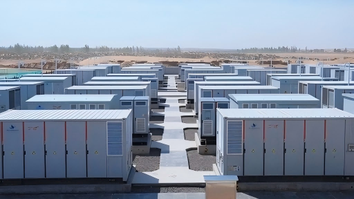
As the current in the reverse-polarity protection circuit of energy storage BMS upgrades from 100A to 300A, the thermal resistance bottleneck of surface-mount Schottky diodes becomes a decisive factor in selection. Starting from loss calculation and the thermal resistance path, this article provides selection criteria for high-current Schottky modules.
SMD Schottky Diodes “Cannot Hold Up”—the Root Cause Is Not VF Itself, but the Impossibility of Specifying Thermal Resistance. When the battery-cluster current exceeds 150 A, heat from an SMD package can only be passively conducted away through PCB copper foil, and the junction temperature cannot be locked down by design calculation. The core value of modular packaging is to turn thermal resistance into an engineering parameter that can be written into a datasheet, verified, and reproduced.
The Loss Accounting: From 20 A to 150 A, How the Thermal-Resistance Bottleneck Emerges
At 20 A and VF = 0.5 V, an SMD Schottky already dissipates 10 W. Ten watts is not unbearable; the problem is that this 10 W must pass through the conduction chain “die → molding compound → solder joint → PCB copper foil → ambient,” and the thermal resistance of this chain depends on copper area, layer count, and airflow conditions—designers cannot obtain a definite Rth(j-a) value from the device datasheet.
When the current rises above 150 A, the loss scales up with I × VF, but the thermal resistance at the end of the conduction chain does not “upgrade” with the current. The junction temperature rapidly approaches its limit, yet engineers have no reliable number to judge “how many degrees are left.” This is precisely the underlying driver for the shift from SMD to modular packaging in high-current reverse-polarity protection loops: not that the module’s VF is lower, but that the module’s thermal resistance can be specified.
The Real Significance of Modularization: Turning “Guessing Thermal Resistance” into “Calculating Junction Temperature”
Taking the typical 100–300 A current range of energy-storage battery clusters as an example, modular packaging establishes a specifiable thermal-resistance conduction path through a metal baseplate. Once designers have Rth(j-c), they can calculate the junction-temperature margin directly by adding P × Rth to the case temperature, without relying on trial and error with PCB copper area.
HS8MBRH300N2X100 (M31H package, 200 V / 300 A / VF 0.75 V / IFSM 2000 A) exactly matches this current range: its 300 A rated current covers the continuous current-carrying requirements of battery-cluster reverse-polarity protection and hot-swap ORing, while its 0.75 V VF is relatively low among 200 V-class modules, bringing the conduction loss at 150–250 A operating current into a calculable and thermally manageable range.