

Is 90% Efficiency Enough for Inverter Welding IGBT Modules?
Defining the “Good-Enough” Boundary in Cost-Sensitive Designs
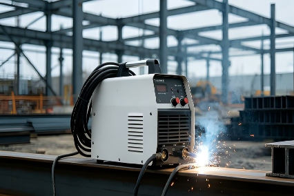
When selecting IGBT modules for inverter welding machines, whether 90% efficiency is sufficient depends on duty cycle, thermal conditions, and cost constraints. Starting from loss composition and typical operating conditions, this article outlines the boundaries of 'sufficient' and a framework for selection decisions.
SiC has generated plenty of attention in welding applications. Public industry sources indicate that SiC solutions can push system efficiency above 93%, while IGBT-based welding machines typically operate in the 85%–90% range. For the high-volume, low- and medium-voltage general-purpose welding market, however, the electricity savings from a 3–5 percentage-point efficiency gain can take years to offset the SiC device premium. A 90% efficiency figure is lower than SiC in absolute terms, yet IGBT-based designs remain mainstream in cost-sensitive welding markets—not because the technology is behind, but because it is good enough for the application.
The more useful question, therefore, is not “should we move to SiC?” but “within an IGBT-based design, what are the good-enough conditions for different topologies and current classes?” Choosing the wrong topology carries a higher cost than choosing the wrong efficiency number.
“Good enough” is not an efficiency value—it is the fit between topology and load profile
The DC bus of an inverter welding machine is typically below 650 V. The 1200 V class provides voltage margin, while the 650 V class can be used directly in low-voltage topologies. Within the same good-enough efficiency range, Six-Pack integration and INPC topology represent two different engineering logics: the former trades integration for system cost and layout simplification; the latter uses the lower switching loss of a low-voltage topology to support higher frequency and higher power density.
Application position | Contribution mechanism | Quantifiable check at selection stage | Corresponding model / option |
Main power stage of medium-power welding machines (1200 V / 75 A class) | Six-Pack integration reduces the number of gate-drive channels and layout area, lowering system BOM and assembly cost | Check VCE(sat) and Eon/Eoff against the junction temperature margin under the continuous load profile; Tjmax 175°C provides the thermal-boundary entry point | HGS75MF120X100 (1200 V / 75 A / Six-Pack, VCE(sat) 1.9 V, VF 2 V) |
Low-voltage high-frequency welding topology (650 V / 150 A class) | INPC topology has significantly lower switching loss than a conventional hard-switched half-bridge at low bus voltage, allowing a higher inverter frequency | Check whether the Eon/Eoff level supports the target switching frequency; Tjmax 150°C defines the thermal boundary for low-voltage operation | 650 V / 150 A INPC option (see IGBT module selection page) |
The difference between the two rows is not “which one is more efficient.” It is the variable that must be locked during selection: the Six-Pack looks at system-cost savings from integration and the thermal margin under continuous medium-power load; the INPC looks at whether the switching-loss level can support a higher frequency, thereby reducing magnetic component size and increasing power density.
Six-Pack: integration is a benefit beyond efficiency
In the medium-power welding segment, the value of a Six-Pack is not just fewer devices on the datasheet. Six switches integrated into one module compress the number of gate-drive channels, busbar layout, and heatsink mounting interfaces at the same time, reducing system-level BOM and assembly labor. For cost-sensitive models, this saving is often more direct than raising efficiency from 90% to 91%.
HGS75MF120X100 offers VCE(sat) 1.9 V and VF 2 V in the 1200 V / 75 A / Six-Pack class. According to the hyperSemi official datasheet, Eon is 5.2 mJ, Eoff is 3.6 mJ, and Tjmax is 175°C. This loss level and thermal boundary correspond to the continuous load profile of medium-power welding machines: there is no need to pay an extra loss penalty for extremely high switching frequency, nor to over-design for an extreme heat flux density. The 175°C junction temperature limit does not mean “it can run hotter”; it provides swing margin for the periodic load fluctuations of a welding machine.
There is no need to compare it with SiC on efficiency. Its good-enough conditions are clear: the power stage prioritizes integration and system cost, the switching frequency sits in the conventional inverter range, and the load is mainly continuous or periodically medium-current.
INPC: low-voltage topology shifts switching loss to another level
The logic of the 650 V / 150 A INPC option is different. In low-bus-voltage welding topologies, the multilevel structure of INPC reduces the voltage stress on the switching devices, so Eon and Eoff can be much lower than those of a conventional half-bridge at the same current class. According to the hyperSemi official datasheet, this class offers VCE(sat) 1.57 V, VF 1.62 V, Eon 0.66 mJ, Eoff 1.28 mJ, and Tjmax 150°C. With turn-on loss below 1 mJ, the increase in switching loss remains manageable when the inverter frequency of a low-voltage welding machine is raised.
But Tjmax of 150°C also defines its boundary: thermal stress under low-voltage operation is usually lower than in high-voltage, high-current scenarios, so 150°C is a matching boundary. If it is forced into a profile with a higher bus voltage and heavier load, the thermal boundary will become the limiting factor before efficiency does. “Good enough” here means that the topology voltage class, switching-frequency target, and thermal boundary align at the same time—not that a single device loss number looks attractive.
The localization window is open, but selection logic cannot be skipped
Industry data show that in 2026, the domestic localization rate of IGBT modules for inverter welding machines in China has exceeded 45%, with low- and medium-voltage general-purpose models approaching 60%. Supply depth is now sufficient to move domestic replacement from “can it be used?” to “how do we select it correctly?” But a rising localization rate does not automatically answer the topology-matching question: Six-Pack and INPC serve different welding power stages and frequency strategies, and applying one “compare VCE(sat)” table to both positions is not engineering-valid.
A more rational order is: first lock the welding machine’s bus voltage, target switching frequency, and load profile; then decide whether the position needs the system-cost benefit of integration or the switching-loss advantage of a low-voltage topology; finally, check the specific model’s VCE(sat), Eon/Eoff, and Tjmax. HGS75MF120X100 and the 650 V / 150 A INPC option stand at the entry points of two different logics; they are not substitutes for each other. A wider range of voltage, current, and topology combinations can be located on the IGBT module selection page according to the actual bus conditions of the welding machine.