Downloads
 Free samples
 TechForum


Induction Heating — How IGBTs Drive the Powerful Performance of Commercial Induction Cookers
 668
668


.png)

.png)


Commercial induction cookers operate based on the principle of electromagnetic induction: they convert utility-frequency AC power into high-frequency AC power (typically 20-40 kHz), generating an alternating magnetic field through the excitation coil. This field induces eddy currents in the metal cookware base, causing it to heat up.
In this power conversion process, the IGBT discrete device acts as a high-speed switch. By frequently and rapidly switching on and off, it converts direct current into high-frequency alternating current. Its switching performance (e.g., speed, losses) directly impacts the appliance’s heating efficiency, power regulation accuracy, and temperature control.
Working Topology: IGBTs in Half-Bridge Resonant Structures
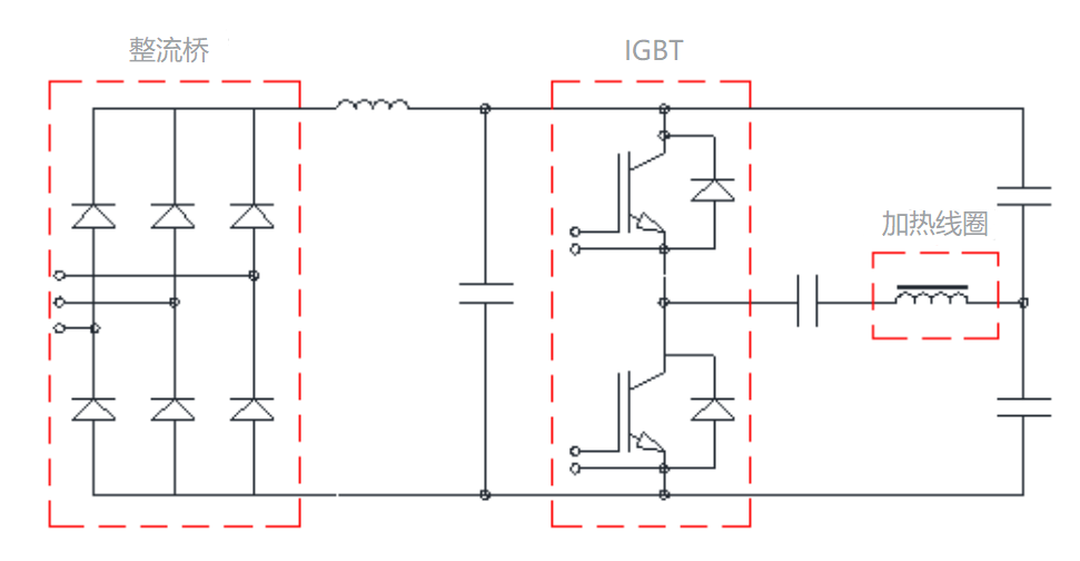
Currently, mainstream commercial induction cookers widely adopt the half-bridge series resonant topology. This structure offers high efficiency and flexible control, making it an ideal choice to leverage the performance of IGBTs. The basic topology is as follows:
Working Process Analysis:
Rectification and Filtering
Mains electricity is rectified via a bridge rectifier and filtered by high-capacity capacitors to obtain smooth DC voltage (Vdc).High-Frequency Inversion
Two HG30T135TPX100 IGBT discrete devices alternately conduct (complementary switching) under the control of drive signals, converting DC power into square-wave AC power.LC Resonance
The square-wave voltage is applied to a series resonant circuit consisting of an excitation coil (equivalent inductance L) and a resonant capacitor (C).When the switching frequency approaches the resonant frequency, the circuit resonates, generating high-amplitude high-frequency current in the coil. This creates a strong alternating magnetic field for heating.Power Regulation
By finely adjusting the IGBTs’ switching frequency (via pulse width modulation), the circuit is tuned to deviate from or approach the resonant point, enabling seamless and continuous output power control.
Low Saturation Voltage (Vce(sat))
Only 2.3V (at Tj=25°C) / 2.8V (at Tj=150°C), reducing conduction losses for higher efficiency and lower heat generation.
Low Switching Losses (Eon/Eoff)
Optimized switching characteristics (Eon=3.0mJ, Eoff=1.5mJ @25°C), suitable for high-frequency operation and minimizing heat dissipation challenges.High Short-Circuit Withstand Capability (tsc=10μs)
Provides sufficient time for protection circuits to activate during abnormalities (e.g., dry heating of cookware), preventing catastrophic failures.Fast Soft Recovery Diode (FRD)
Low reverse recovery charge (Qrr) of the built-in diode effectively suppresses turn-off voltage spikes and oscillations, reducing EMI and enhancing reliability.Low Thermal Resistance (RthJC=0.36K/W)
Excellent thermal conductivity slows junction temperature rise, enabling prolonged high-temperature operation and extended lifespan.
power | Package | 650V | 1200V |
500V-5000W | TO-247 | HG75T65LX100 | HG25T120LX100 |
HG30T135LX100 | |||
HG40T120LX100 | |||
TO-3PN | HG25T120TPX100 | ||
HG30T135TPX100 | |||
HG40T120TPX100 | |||
10KW-30KW | 34MM | HGF75MA65X100 | HGF75MA120X100 |
HGF100MA120X100 | |||
HGF150MA120X100 | |||
62MM | HGF150MB120X100 | ||
HGF200MB120X100 | |||
HGF300MB120X100 |
Auxiliary circuit section:
Product | Parameter |
Rectifier Bridge | 2A~35A,50V~1000V |
TVS | 400W~50KW,5.0V~550V |
Rectifier diode | 0.2A~10A,50V~5000V |
Fast Recovery diode | 0.2A~6A,50V~5000V |
Super fast recovery diode | 1A~6A,50V~1000V |
Schottky diode | 0.25A~8A,20V~210V |
Power diode | 7A~30A,20V~150V |
Zener Diode | 1.8V~200V |
Switching diode | 20V~75V |